| An ADXL202 break-out board. |
|
I've wanted to play around with the ADXL202 acceletometer ever since I first saw a DIY self-balancing robot on the web. The ADXL202 accelerometer comes in an incredibly small component package. So small that it at first scared me from trying to solder it onto a board. A few months ago I bought me a nice and small soldering iron with a tip not much larger than a bulletin board pin, so now it's time to make a break-out board for the accelerometer. 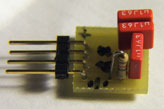 click to enlarge... Here's a view of the accelerometer mounted on the board. Duh! that's small: 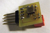 click to enlarge... The board is supplied with +5v and ground. There are two output pins on the board. They each output the square shaped signal seen on the picture below. The duty cycle of the signal corresonds to the acceleration in the X- and Y- direction. The duty cycle grows when the accelerometer is moved in the one direction, and shrinks when moved in the opposite direction.: 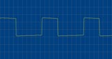 click to enlarge... Along with the accelerometer there is mounted 3 capacitors and a resistor. The resistor defines the output signal frequency. I used a 1.2 megaohm resistor, giving me a frequency of around 15 ms pr. cycle. 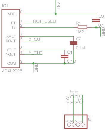
The capacitors C1 and C2 are used to define the smoothing of the measured acceleration of the ADXL202. 0.1uf seems to do the trick for general application of the accelerometer The last capacitor, C3, is used to dampen noise on the logic supply signal to the accelerometer. If you want to make your own ADXL202 breakout board, then go ahead and download my Eagle schematic and PCB on the link below: click to download... That's about it. Get on soldering and start playing with the ADXL202 accelerometer. It's a super cool and easy sensor to include in your next project! Thank you for reading! |