| The CNC mill project |
|
In this article I'll document the all-the-way homebuilt CNC milling project that two of my good friends and I have undertaken. (visit their site at www.ackw.dk) The CNC mill has been built from scratch. We've even made our own controller board to drive the stepper motors that power the axis of the CNC mill. We started the project by CAD engineering the harware platform. The entire mill platform has been built using 15 mm thick aluminum plating. We bought a 1.5 m X 1 m plate of aluminium and due to its size we had to cut it out in smaller sections in order to process it further. This was done using a very low-tech approach: 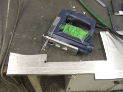 click to enlarge... After cutting the plate to small bits and pieces, the pieces were milled down with the use of our good old manual milling machine: 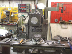 click to enlarge... Alter hours and hours in the workshop (every tuesday and many weekends over a 6 months period) we were finally done with the construction of the haradware platform. A picture of the finished platform as well as a time-lapse video of a typical day in the workshop can be seen below. (By the way, you can download my Windows 2000/XP based homebrew time-lapse software at my software section) 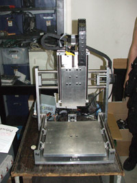 click to enlarge... 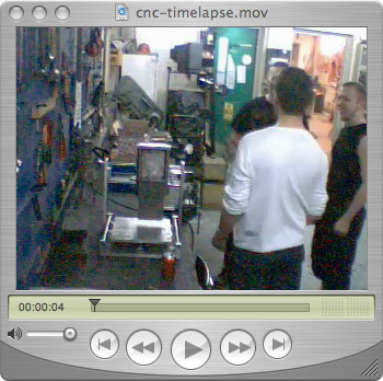
So... What makes the CNC mill tick? It's the controller board. I don't want to go into details on how the CNC controller board has been designed. This is just a quick overview of the project, and a more detailed description of each subsystem will be written some day. The board is based around a central PIC controller, the PIC18f2220. An optocoupler bridge isolate the parallel port cable from a PC from the rest of the board. You cannot see this bridge on the picture below as it is SMD mounted on the back site of the board. 3 arrays of FET transistors are used to provide motor control, and the firmware written to the PIC micro controller is compliant with commercial CNC software such as Mach3 and turbocnc. Here's the board: 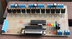 click to enlarge... Let's take a look at a video of some early testing. 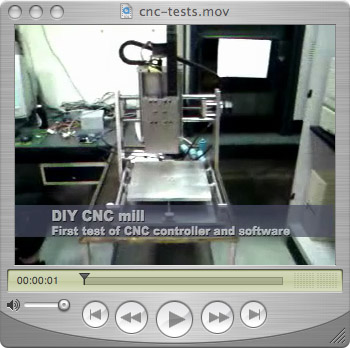
click to enlarge... Right now you probably wonder where the tool spindle is. We used a bosch grinder as a tool spindle. On the video above it hasen't been installed yet, but here it is: 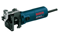 click to enlarge... Here's one final video of a milling job of a 2D logo in plywood: 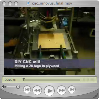
click to enlarge... And one last picture. It's a nice 3D job that we've milled. A plano-concave hacked gadgets logo thingy. It is drawn in 3D in ProEngineer Wildfire 3 and the CAM (computer aided manufactoring) job has been made in ProE as well. It's not much bigger than a matchbox, so the quality of the parts we can produce on the mill is very good! 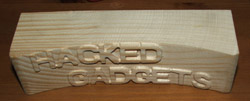 click to enlarge... We have made some tests in aluminum. The mill has no problem whatsoever to mill in aluminum and other faily soft metals. I have not made any parts in metal yet as we want to shield the ball bearing guides before we really start to machine metals. That's about it for now. The contents of this page was rushed, so I hope to do a complete rewrite some time in the future, but when that might be is a good question. Don't forget to visit my blueprints section where I have documented many of my other projets such as my 3D scanner, my laser beam analyzer and much more. Please visit my sponsor links in the left hand margin. That's what pays the web hosting bills and I'd be sad to be forced to stop publishing my work. Thank you for reading! |